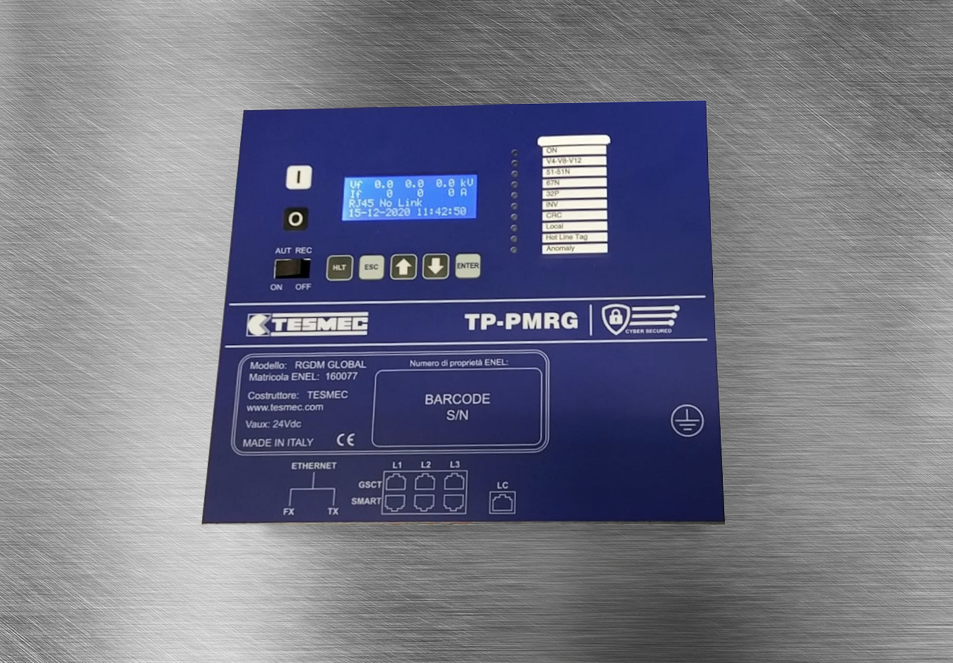
TP-PMRG
PROTECTION AND MEASUREMENT DEVICE FOR SECONDARY SUBSTATION
Tesmec TP-PMRG is a protection and measurement relay for the automation of remote controlled distribution substations, operated in medium voltage. Enables automatic fault location, isolation and mains power recovery. It integrates protection functions, measurement and telemetry, automatic paralleling, fault recording, analysis and monitoring of the quality of the electrical service. It communicates with other devices on the network according to the IEC 61850 protocol. It complies with the latest cyber-security standards.
Technical Specifications
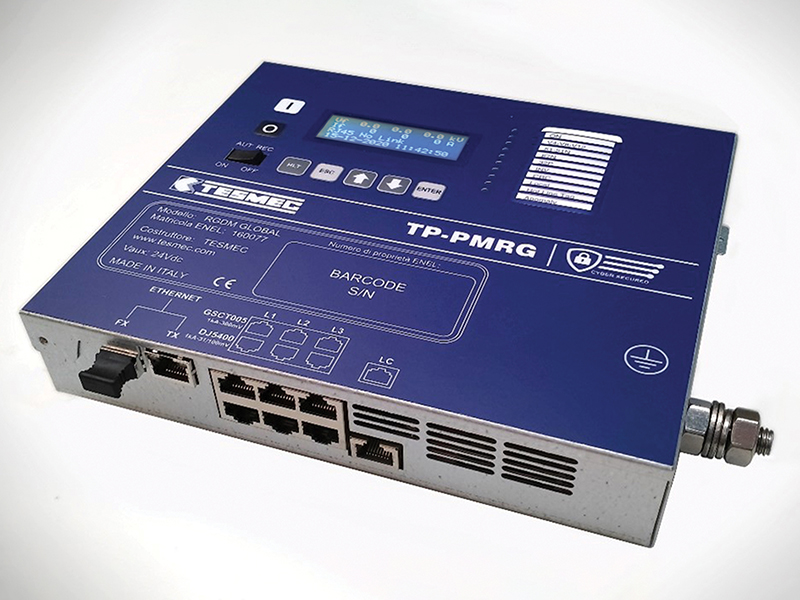
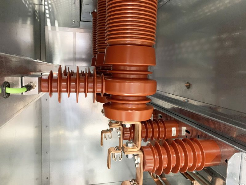
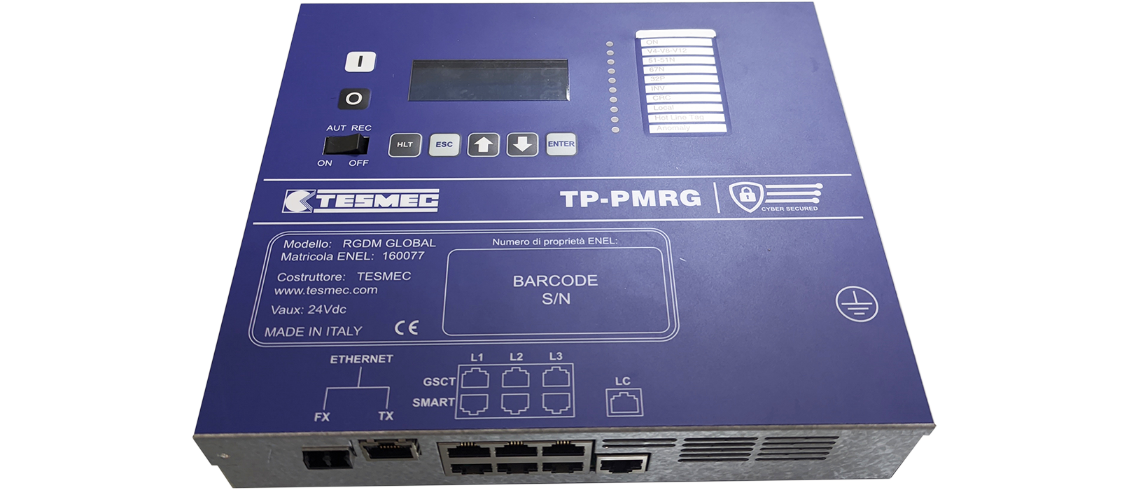
The device is designed for installation in a remote-controlled medium voltage (MV) secondary substation, equipped with an SF6 or air-insulated switch, a line disconnector, and an air-insulated disconnector. The metal enclosure features a hinged closure for wiring access and supports vertical installation. The TP-PMRG relay can interface with three low-power current and voltage transducers (LPITs, compliant with IEC 61869), both active and passive, using shielded cables with RJ45 connectors. Separate inputs are provided for transducers compliant with Enel Global standards DJ5400 and GSCT005.
There are two more independent Ethernet ports: one in copper (RJ45) and one optical 100base-FX (LC). It is equipped with:
- 2 control relays;
- 3 signaling relays;
- 6 optoisolated inputs.
Digital inputs and outputs can be configured via software and programmable with PLC logic. The device integrates the functions of the Web Server and has an isolated and configurable DC telemetry output (4-20 mA).
Technical data
GENERAL RATINGS
| Capacitive sensor operating voltage MV | 0,4 o 6÷24 kV ±50% |
| Operating frequency | 50 – 60 Hz ± 5% |
| Frequency measurement accuracy (VF/ VS) | 5 mHz |
| Max three phase short-circuit current | 16 kA |
| Operating temperature | -25 °C ÷+75 °C |
| Supply voltage | 24V dc (guaranteed from 15 V to 35 V). Protected against polarity inversion |
PROTECTION FUNCTIONS (ANSI/IEEE)
| 67/51 (overcurrent) | Independent time or inverse time (NIT/VIT/EIT/LIT) and 2ndH REST |
| 51N (earth overcurrent) | Independent time or inverse time (NIT/VIT/EIT/LIT) and 2ndH REST |
| 67N (phase/earth directional overcurrent) | Independent time or inverse time (NIT/VIT/EIT/LIT) and 2ndH REST |
| 32P (directional/reverse power) | Independent time |
| 27/27DC (undervoltage) | Independent time or inverse time |
| 50BF (breaker failure) | Independent time |
| 59/59N (maximum voltage) | Independent time or inverse time |
| EAC 81 (frequency) | Independent time (max, min, derived and block functions) |
| 79 (auto reclosing CA) | Independent time |
| 25 (synchro-check device) | Synchronus parallel, asynchronus, synchronus + asynchronus |
VOLTAGE ANALOG INPUT (50 Hz / 60 Hz)
| Transformation Ratio (linear sensor) | 10 kV : 1 V [RMS] (primary 230V:1V [RMS]) |
| Transformation Ratio (capacitive sensor) | Calibrated via SW for 0,4 o 6÷24 kV ±50% |
| Primary full-scale | 72 kV/√3 [RMS] |
| Bandwidth (-3dB) | 2500 Hz (linear and capacitive) |
| Linear input impedance | Ra=2 MOhm 0.5% (Cz<10 pF) |
| Capacitive input impedance | Ca=220 nF 5% (Rz=2 MOhm) |
| Nominal error (10kV) | ≤ 0.2% of measured value |
| Analog resolution | 256 samples/period (16bit) |
CURRENT ANALOG INPUT (50 Hz / 60 Hz)
| Transformation ratio (linear sensor) | 1.0 kA : 300 mV / 1 V kA: 100mV / 1.0 kA-: 31 mV [RMS] |
| Transformation ratio (Rogowski sensor) | 1.0 kA : 300mV / 1.0 kA: 100 mV / 1.0 kA : 31 mV [RMS] |
| Primary full-scale | ≤10ms |
| Bandwidth (-3dB) | 9 kA [RMS] |
| Linear input impedance | DC : 2500 Hz (linear) e 0.5 Hz : 2000 Hz (Rogowski) |
| Rogowski input impedance | Ra=20 kOhm 0.5% (Cz<10 pF) |
| Nominal error (1.0 kA) | ≤0.2% of measured value |
| Analog resolution | 256 samples/period (16bit) |